3.4 DSSD Front-Back Correlation Part I
3.4.1 Front-Back Energy Correlation
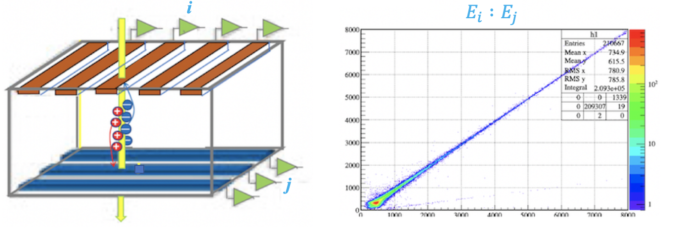
When a single charged particle hits the intersection pixel of front strip $X_i$ and back strip $Y_j$ of the DSSD, electrons and holes drift toward opposite electrodes. For an ideal single-pixel hit event, the amount of charge collected on the front and back sides is equal, corresponding to the same true deposited energy $E_{\mathrm{true}}$:
$$ E_{\mathrm{true}} = E_{x,i} = E_{y,j} $$
In the Data Acquisition (DAQ) system, the recorded observables are the raw ADC amplitudes $A_{x,i}$ and $A_{y,j}$. Assuming linear electronics response, they can be expressed as:
$$ E_{x,i} = g_{x,i} A_{x,i} + o_{x,i} $$
$$ E_{y,j} = g_{y,j} A_{y,j} + o_{y,j} $$
Because the gains $g$ and offsets $o$ vary among different strips, the raw ADC amplitudes cannot be directly compared. Before performing an absolute radioactive source calibration, it is essential to first establish a unified Relative Energy Scale $E^{(\mathrm{rel})}$ within the detector.
3.4.2 Relative Energy Calibration
To construct this unified scale, we select the front strip $r$ with the highest statistics and most stable response (denoted as $X_{r}$) as the baseline reference, and define its raw ADC amplitude directly as the relative energy scale for the entire detector:
$$ E^{(\mathrm{rel})} \equiv A_{x,r} \quad \Longrightarrow \quad k_{x,r} = 1, \ b_{x,r} = 0, \ \sigma(k_{x,r})=0, \ \sigma(b_{x,r})=0 $$
For any other strip, the goal is to extract its Current Global Parameters $(k, b)$ to map its raw signal onto this unified scale:
$$ E_{x,i}^{(\mathrm{rel})} = k_{x,i} A_{x,i} + b_{x,i} \tag{1} $$
$$ E_{y,j}^{(\mathrm{rel})} = k_{y,j} A_{y,j} + b_{y,j} \tag{2} $$
The Local Pixel Bridge
The physical connection between strips relies on local pixel parameters. For a clean single-pixel event at $(i,j)$, a 2D linear fit yields the local relation:
$$ A_{x,i} = s_{ij} A_{y,j} + t_{ij} \tag{3} $$
By substituting this local bridge into the global scale equations, the relative scale can be propagated. To make this clear for algorithmic implementation, we distinguish between the Current Global State of a source strip (Right-Hand Side) and the Path-Specific Candidate generated for the target strip (Left-Hand Side).
Forward Propagation ($X \to Y$): Using the current global parameters of $X_i$ ($k_{x,i}, b_{x,i}$), we generate a candidate for $Y_j$: $$k_{y,j}^{[i]} = k_{x,i} s_{ij}, \qquad b_{y,j}^{[i]} = k_{x,i} t_{ij} + b_{x,i} \tag{4}$$
Reverse Propagation ($Y \to X$): Using the current global parameters of $Y_j$ ($k_{y,j}, b_{y,j}$), we generate a candidate for $X_i$: $$k_{x,i}^{[j]} = \frac{k_{y,j}}{s_{ij}}, \qquad b_{x,i}^{[j]} = b_{y,j} - \frac{k_{y,j} t_{ij}}{s_{ij}} \tag{5}$$
Propagation Step
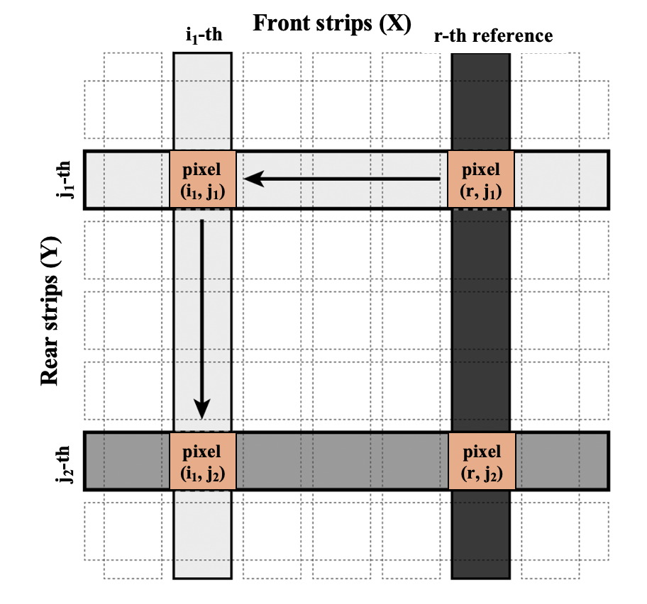
Starting with $i=r$, since $X_r$ is the baseline ($k_{x,r} = 1, b_{x,r} = 0$), we can use the local fit of pixel $(r, j_1)$ and Equation (4) to obtain the calibration coefficients $(k_{y,j_1}, b_{y,j_1})$ for the back strip $Y_{j_1}$. Subsequently, using the newly calibrated $Y_{j_1}$ and pixel $(i_1, j_1)$, we can reversely derive the coefficients for the front strip $X_{i_1}$ via Equation (5). By repeating this process, the newly calibrated $X_{i_1}$ can further propagate the scale to other back strips like $Y_{j_2}$, achieving parameter coverage across the entire detector in a chain reaction.
Error Propagation
The local pixel fits inherently contain uncertainties $\sigma(s_{ij})$ and $\sigma(t_{ij})$. According to the law of error propagation, the variances of these candidate parameters depend on both the local fit errors and the current global uncertainties of the source strip:
Variances for the candidate parameters of $Y_j$ (from source $X_i$): $$\sigma^2\!\left(k_{y,j}^{[i]}\right) \approx s_{ij}^2\,\sigma^2(k_{x,i}) + k_{x,i}^2\,\sigma^2(s_{ij})$$ $$\sigma^2\!\left(b_{y,j}^{[i]}\right) \approx t_{ij}^2\,\sigma^2(k_{x,i}) + k_{x,i}^2\,\sigma^2(t_{ij}) + \sigma^2(b_{x,i})$$
Variances for the candidate parameters of $X_i$ (from source $Y_j$): $$\sigma^2\!\left(k_{x,i}^{[j]}\right) \approx \frac{\sigma^2(k_{y,j})}{s_{ij}^2} + \frac{k_{y,j}^2}{s_{ij}^4}\sigma^2(s_{ij})$$ $$\sigma^2\!\left(b_{x,i}^{[j]}\right) \approx \sigma^2(b_{y,j}) + \left(\frac{t_{ij}}{s_{ij}}\right)^2\!\sigma^2(k_{y,j}) + \left(\frac{k_{y,j}}{s_{ij}}\right)^2\!\sigma^2(t_{ij}) + \left(\frac{k_{y,j}t_{ij}}{s_{ij}^2}\right)^2\!\sigma^2(s_{ij})$$
(Note: The variables like $k_{x,i}$ and $\sigma^2(k_{x,i})$ on the right side of the equations simply refer to the global values obtained from the previous iterative process).
Multi-path Issue & Inverse-Variance Weighting
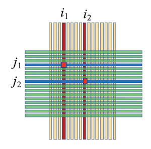
The grid-like pixel structure of the detector means that the propagation of the calibration scale is not a single linear chain, but rather a multi-path network. A single strip will receive multiple candidate parameters simultaneously.
Example of Multi-path Propagation: Let $X_{\mathrm{ref}}$ be the absolute baseline.
- Step 1: $X_{\mathrm{ref}}$ propagates forward to back strips $Y_7, Y_{12},$ and $Y_{20}$. Since $X_{\mathrm{ref}}$ is their only calibrated source at this moment, they accept these candidates as their current global parameters: $k_{y,7}, k_{y,12}, k_{y,20}$.
- Step 2: Now consider a target front strip $X_5$ that intersects all three of these back strips. $X_5$ will receive three distinct candidate parameters through reverse propagation:
- From $Y_7$: calculates candidate $k_{x,5}^{[7]}$ using the global $k_{y,7}$ obtained from the previous process.
- From $Y_{12}$: calculates candidate $k_{x,5}^{[12]}$ using the global $k_{y,12}$ obtained from the previous process.
- From $Y_{20}$: calculates candidate $k_{x,5}^{[20]}$ using the global $k_{y,20}$ obtained from the previous process.
To rigorously solve this, we define:
- Set $\mathcal{C}_j$: The set of all already-calibrated front strips $i$ that intersect with back strip $Y_j$.
- Set $\mathcal{C}_i$: The set of all already-calibrated back strips $j$ that intersect with front strip $X_i$.
Weighted Fusion Algorithm (Overall SCM): Facing multiple candidates, the algorithm employs Inverse-Variance Weighting. Candidates generated from paths with tighter local pixel correlations or better-calibrated source strips will have smaller variances, and thus are assigned larger weights.
1. Global parameter fusion for back strip $Y_j$: Calculate the weights for the candidates provided by all front strips $i \in \mathcal{C}_j$: $$w_{ij}^{(k)} = \frac{1}{\sigma^2\!\left(k_{y,j}^{[i]}\right)}, \qquad w_{ij}^{(b)} = \frac{1}{\sigma^2\!\left(b_{y,j}^{[i]}\right)}$$
Perform a weighted sum to update the Current Global Parameters for $Y_j$: $$k_{y,j} = \frac{\sum_{i \in \mathcal{C}_j} w_{ij}^{(k)}\,k_{y,j}^{[i]}}{\sum_{i \in \mathcal{C}_j} w_{ij}^{(k)}}, \qquad \sigma^2(k_{y,j}) = \frac{1}{\sum_{i \in \mathcal{C}_j} w_{ij}^{(k)}}$$ $$b_{y,j} = \frac{\sum_{i \in \mathcal{C}_j} w_{ij}^{(b)}\,b_{y,j}^{[i]}}{\sum_{i \in \mathcal{C}_j} w_{ij}^{(b)}}, \qquad \sigma^2(b_{y,j}) = \frac{1}{\sum_{i \in \mathcal{C}_j} w_{ij}^{(b)}}$$
2. Global parameter fusion for front strip $X_i$: Similarly, calculate the weights for the candidates provided by all back strips $j \in \mathcal{C}_i$: $$w_{ji}^{(k)} = \frac{1}{\sigma^2\!\left(k_{x,i}^{[j]}\right)}, \qquad w_{ji}^{(b)} = \frac{1}{\sigma^2\!\left(b_{x,i}^{[j]}\right)}$$
Update the Current Global Parameters for $X_i$: $$k_{x,i} = \frac{\sum_{j \in \mathcal{C}_i} w_{ji}^{(k)}\,k_{x,i}^{[j]}}{\sum_{j \in \mathcal{C}_i} w_{ji}^{(k)}}, \qquad \sigma^2(k_{x,i}) = \frac{1}{\sum_{j \in \mathcal{C}_i} w_{ji}^{(k)}}$$ $$b_{x,i} = \frac{\sum_{j \in \mathcal{C}_i} w_{ji}^{(b)}\,b_{x,i}^{[j]}}{\sum_{j \in \mathcal{C}_i} w_{ji}^{(b)}}, \qquad \sigma^2(b_{x,i}) = \frac{1}{\sum_{j \in \mathcal{C}_i} w_{ji}^{(b)}}$$
By continuously iterating this computational loop—"Extract parameters from previous process $\to$ Propagate Path Candidates $\to$ Weighted Fusion to Update Global"—across the entire grid until the parameters $k$ and $b$ stop changing, the algorithm achieves an accurate, globally optimized relative energy calibration for the entire DSSD.
Multi-hit position matching
The primary physical purpose of introducing relative normalization is to resolve the Pairing Ambiguity that occurs when multiple particles cross the detector simultaneously.
Assume two particles strike the detector at the same time, producing true hit points at $(X_1, Y_1)$ and $(X_2, Y_2)$ with distinct energies ($E_1 \neq E_2$). The readout system records signals from front strips $X_1, X_2$ and back strips $Y_1, Y_2$. Relying solely on geometric topology, it is impossible to distinguish whether the genuine physical combination is $\{(X_1, Y_1), (X_2, Y_2)\}$ or the spurious "ghost" combination $\{(X_1, Y_2), (X_2, Y_1)\}$.
By normalizing all strip signals to the unified scale $E^{(\mathrm{rel})}$, we can construct a residual criterion based on the physical principle of front-back energy consistency:
$$ \Delta E = |E^{(\mathrm{rel})}_{x} - E^{(\mathrm{rel})}_{y}| $$
Physical Matching Criterion: For a correctly paired front-back strip combination, their normalized energy difference $\Delta E$ should be minimized (approaching zero). Therefore, relative normalization serves as an essential prerequisite for precise multi-particle identification and position reconstruction.
3.4.1 Detector Setup
ROOT File: data_16C.root
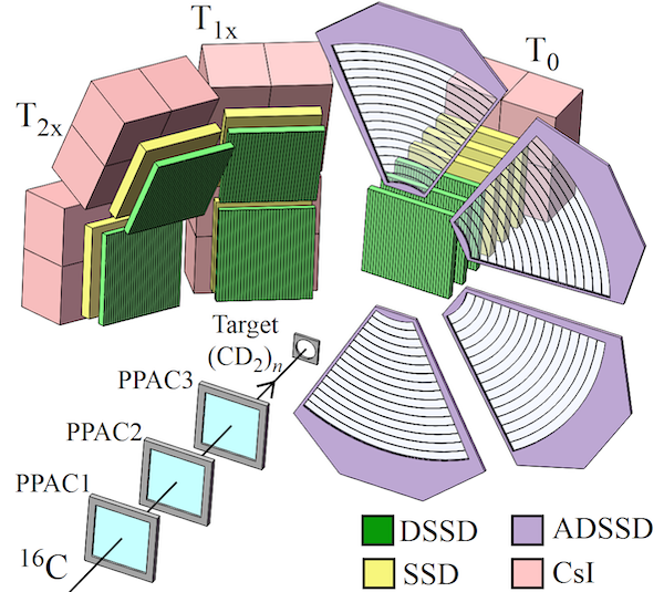
- Reaction System: 25 MeV/A $^{16}$C + $^9$Be, measuring large-angle multiple charged particles produced from the fragmentation of $^{16}$C.
- Detector Array: A telescope array consisting of 3 DSSDs + CsI, positioned at zero degrees behind the target.
- D1, D2, and D3 are all double-sided silicon strip detectors with 32 (X) $\times$ 32 (Y) strips.
- Strip width: 2 mm, inter-strip spacing: 0.1 mm.
- Hardware Trigger: Requires at least two hits on the X-side of both D1 and D2 (Multiplicity $\ge$ 2).
- Data Preprocessing: Pedestal events have been removed.
Branch:
// xenergy, yenergy, xtime (Array of 32 for each detector)
d1x[32], d1y[32], d1t[32];
d2x[32], d2y[32], d2t[32];
d3x[32], d3y[32], d3t[32];

// hit multiplicity, energy, time, strip ID (Compact arrays based on hits)
d1xhit, d1xe[d1xhit], d1xt[d1xhit], d1xs[d1xhit];
d2xhit, d2xe[d2xhit], d2xt[d2xhit], d2xs[d2xhit];
d3xhit, d3xe[d3xhit], d3xt[d3xhit], d3xs[d3xhit];
d1yhit, d1ye[d1yhit], d1yt[d1yhit], d1ys[d1yhit];
d2yhit, d2ye[d2yhit], d2yt[d2yhit], d2ys[d2yhit];
d3yhit, d3ye[d3yhit], d3yt[d3yhit], d3ys[d3yhit];
TFile *ipf = new TFile("./data/data_16C.root");
TTree *tree = (TTree*)ipf->Get("tree");
TCanvas *c1 = new TCanvas("c1","c1");
Multiplicity for X and Y Sides
The hardware trigger condition ($M \ge 2$) ensures that the vast majority of events have a front and back multiplicity of 2 or higher. Events with energy below the pedestal threshold have been filtered out.
tree->Draw("d1xhit: d1yhit>>(15, 0, 15, 15, 0, 15)", "", "colz");
gPad->SetLogz();
c1->Draw();
- Most of these $M \ge 2$ events are Charge Sharing events between adjacent strips, while a small fraction consists of genuine multi-particle incident events.
tree->Scan("d1xe: d1xs: d1ye: d1ys", "", "", 10, 1);
***********************************************************************
*    Row   * Instance *      d1xe *      d1xs *      d1ye *      d1ys *
***********************************************************************
*        1 *        0 *      4800 *        17 *      5775 *        18 *
*        1 *        1 *       982 *        18 *           *           *
*        2 *        0 *      3069 *        23 *      3352 *        11 *
*        2 *        1 *       341 *        24 *       111 *        10 *
*        3 *        0 *      5325 *        23 *      4522 *        15 *
*        3 *        1 *           *           *       922 *        16 *
*        4 *        0 *      5822 *        21 *      5688 *        15 *
*        4 *        1 *           *           *       271 *        14 *
*        5 *        0 *      4048 *        11 *      5213 *        12 *
*        5 *        1 *      1149 *        12 *           *           *
*        6 *        0 *      3719 *        14 *      4255 *        16 *
*        6 *        1 *       374 *        13 *           *           *
*        7 *        0 *      4546 *        12 *      4961 *         9 *
*        7 *        1 *       297 *        11 *           *           *
*        8 *        0 *      4051 *        22 *      3877 *         9 *
*        8 *        1 *           *           *       329 *        10 *
*        9 *        0 *      6720 *        13 *      6513 *        12 *
*        9 *        1 *       142 *        10 *       418 *        13 *
*        9 *        2 *       109 *        14 *           *           *
*       10 *        0 *      3873 *        20 *      3007 *         8 *
*       10 *        1 *           *           *       974 *         9 *
***********************************************************************
Front-Back Correlation
A clear linear correlation band is observed in the central region. However, prominent scattered points outside this band result from Charge Sharing—where the deposited energy splits between adjacent strips, causing the energy recorded in a single strip to be less than the total deposited energy.
gPad->SetLogy(0);
tree->Draw("d1x[12]: d1y[13]>>(1000, 0, 8000, 1000, 0, 8000)", "", "colz");
c1->Draw();//front-back correlation
X-Y Correlations Unaffected by Adjacent Strip Energy Sharing
To mitigate the impact of energy sharing between adjacent strips, two approaches are traditionally considered:
1. Global Single Multiplicity Requirement: Require exactly one hit on both X and Y sides (xhit==1 && yhit==1). This effectively eliminates scattered points but results in severely low event statistics due to our specific hardware trigger condition ($M \ge 2$).
c1->Clear();
TCut chit1 = "d1xs==12 && d1ys==13 && d1xhit==1 && d1yhit==1";
tree->Draw("d1xe: d1ye>>(1000, 0, 8000, 1000, 0, 8000)", chit1, "colz");
c1->Draw();
2. Local Isolation Cut (Anti-coincidence Condition): Instead of restricting global multiplicity, strictly require that the selected pixel has no signal in its immediate spatially adjacent strips.
- Use a threshold of
< 50channels (representing the hardware pedestal/noise limit). Ensuring neighboring strips are below this threshold topologically guarantees no charge sharing. - For
d1x[12]: Strips 11 and 13 must have no signal (< 50). - For
d1y[13]: Strips 12 and 14 must have no signal (< 50).
Applying this local isolation condition significantly recovers usable event statistics while maintaining high purity of the linear response.
c1->Clear();
TCut cveto = "d1x[11]<50 && d1x[13]<50 && d1y[12]<50 && d1y[14]<50"; // no sharing
TCut c1213 = "d1x[12]>200 && d1y[13]>200 && d1y[13]<8000" && cveto;
tree->Draw("d1x[12]: d1y[13]>>h2(1000, 0, 8000, 1000, 0, 8000)", c1213, "colz");
c1->Draw();
1. Extracting Unbinned Data for Regression
To extract the exact mathematical correlation, we must perform an unbinned regression. We bypass the binned TH2 histogram and directly map the purified TTree events into a TGraph.
TGraph *gr = new TGraph(tree->GetSelectedRows(), tree->GetV2(), tree->GetV1());
gr->SetMarkerSize(0.2);
gr->Draw("A*");
c1->Draw();
2. Standard vs. Robust Regression
Standard Least Squares (pol1): Severely biased by residual, uncleaned cross-talk outliers. These sparse extreme points act as "levers," pulling the fit away from the true diagonal.
Robust Fitting ("ROB"): ROOT's robust fitting utilizes Least Trimmed Squares to automatically down-weight extreme outliers not originating from the main data-generating process.
ROBUST REGRESSION
In the presence of outliers that do not come from the same data-generating process as the rest of the data, least squares estimation is inefficient and can be biased. Robust regression methods are designed to be not overly affected by violations of assumptions by the underlying data-generating process. ROOT supports robust fitting for polynomial functions using the "ROB" option.
https://root.cern/doc/master/fitLinearRobust_8C.html
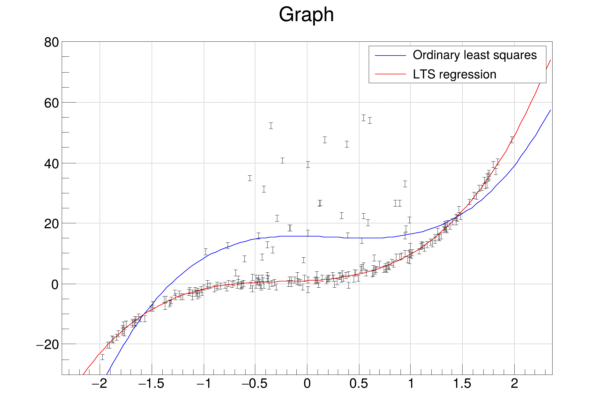
ROOT only supports robust fitting for polynomial functions.
// 1. Standard Fit (Least Squares)
TF1 *fStd = new TF1("fStd", "pol1", 200, 8000);
fStd->SetLineColor(kRed);
gr->Fit(fStd, "RQ");

// 2. Robust Fit (Least Trimmed Squares)
TF1 *fRob = new TF1("fRob", "pol1", 200, 8000);
fRob->SetLineColor(kBlue);
fRob->SetLineWidth(1);
// The "+" option adds the new function to the graph's list, preserving the previous one
gr->Fit(fRob, "R+ ROB Q");

// Draw the graph with points
gr->Draw("A*");

// 3. Add Legend for visual comparison
// (Positioned at top-left to avoid overlapping the y=x diagonal data)
TLegend *leg = new TLegend(0.15, 0.75, 0.45, 0.88);
leg->SetBorderSize(0);
leg->AddEntry(fStd, "Standard Fit (Pulled by outliers)", "l");
leg->AddEntry(fRob, "Robust Fit (Resists outliers)", "l");
leg->Draw();

c1->Draw();
3. Residual Distribution & The "Density Trap"
Let's examine the robust fit's residual distribution: $Y - (p_1 \cdot X + p_0)$.
Even with robust fitting, a slight curvature at high energies remains. This is not a physical nonlinearity of the amplifier. It is a statistical artifact caused by the Density Weight: the overwhelmingly high statistics of low-energy fragments deeply anchor the cost function, slightly compromising the mathematically correct high-energy slope.
// Extract the parameters from the Robust Fit
double p0 = fRob->GetParameter(0);
double p1 = fRob->GetParameter(1);

// Construct the draw command for the residual: Y vs (X - (p1*Y + p0))
TString stree;
stree.Form("d1y[13]:d1x[12]-(%f*d1y[13]+%f)>>ha(100,-40,40,1000,0,8000)", p1, p0);

// Ensure the pad is cleared and ready for a 2D color plot
c1->Clear();
tree->Draw(stree.Data(), c1213, "colz");
c1->Draw();
Assignment
Save the highly purified single-pixel events from DSSD 1/2/3—strictly applying the local isolation cut to exclude adjacent charge sharing—into structured d1/2/3xy.root files. These files will serve as the data foundation for automated full-array relative calibration.
1. Global 2D Correlation Filter (cut1/2/3.C)
Create a rough geometric boundary to enclose the main $Y \approx X$ diagonal band. Draw a 2D scatter plot under ideal clean conditions (xhit==1 && yhit==1), use the ROOT TBrowser Graphical Cut to draw a polygon, and save it as a macro (e.g., cut1.C). This topologically rejects massive far-field noises.
2. Event Extraction Code Structure
// Load the global 2D graphical filter
gROOT->Macro("./data/cut1.C");
TCutG *cut1 = (TCutG*)gROOT->GetListOfSpecials()->FindObject("cut1");

// Helper function: Ensure strip is isolated (neighbors < pedestal threshold)
bool IsStripIsolated(Int_t* energyArray, int stripId) {
    if (stripId > 0 && energyArray[stripId - 1] > 50) return false;
    if (stripId < 31 && energyArray[stripId + 1] > 50) return false;
    return true;
}

// ... [Initialize TFile, TTree, branches] ...

TFile *fout = new TFile("d1xy.root", "RECREATE");
TTree *tout = new TTree("tree", "Purified XY Correlation");
Int_t ix, iy, xe, ye;
// ... [Branch bindings for ix, iy, xe, ye] ...

for(Long64_t jentry=0; jentry<nentries; jentry++) {
    tree->GetEntry(jentry);

    for(int i=0; i<32; i++) {
        if(d1x[i] < 200 || !IsStripIsolated(d1x, i)) continue; // X criteria

        for(int j=0; j<32; j++) {
            if(d1y[j] < 200 || !IsStripIsolated(d1y, j)) continue; // Y criteria

            if(!cut1->IsInside(d1x[i], d1y[j])) continue; // Global 2D limit

            ix = i; iy = j; xe = d1x[i]; ye = d1y[j];
            tout->Fill();
        }
    }
}
fout->Write(); fout->Close();
Expected results
TCanvas *c1 = new TCanvas("c1","c1");
TFile *fin = new TFile("./data/d1xy.root");
TTree *tree =(TTree *)fin->Get("tree");
tree->Draw("ye:xe>>(4000,0,8000,4000,0,8000)","","colz");
c1->SetLogz();
c1->Draw();
Warning in <TCanvas::Constructor>: Deleting canvas with same name: c1
Bootstrapping Relative Calibration Demo
Once the pure single-pixel combinations are saved in d1xy.root, validating the theoretical Relative Energy Calibration becomes extremely streamlined. We can propagate a single reference scale across the array.
The main demo MultiPathDemo() orchestrates the theoretical example:
$$X_{15} \xrightarrow{\text{Forward}} \{Y_7, Y_{12}, Y_{20}\} \xrightarrow{\text{Reverse}} X_5 \xrightarrow{\text{Fusion}} \text{Final } (k_{x,5}, b_{x,5})$$
It consists of five functional blocks:
| Block | Function | Purpose |
|---|---|---|
| Data Structures | StripParam, PixelFit |
Store strip global state $(k,b,\sigma^2)$ and local pixel bridge $(s,t,\sigma^2)$ separately |
| Propagation Engine | ForwardPropagate, ReversePropagate |
Apply Equations (4)-(5) with full error propagation |
| Fusion Engine | FuseCandidates |
Inverse-variance weighted average of multi-path candidates |
| Fitting Helper | GetPixelRelation |
Extract local pixel bridge via robust regression |
| Visualization | DrawValidation |
Compare raw ADC vs calibrated energy in 2D histograms |
Implementation
#include <iostream>
#include <vector>
#include <cmath>
#include "TFile.h"
#include "TTree.h"
#include "TGraph.h"
#include "TF1.h"
#include "TH2F.h"
#include "TCanvas.h"
#include "TStyle.h"

using namespace std;
// ============================================
// Block 1: Data Structures
// ============================================

// Current Global Parameters for a strip
struct StripParam {
    double k = 1.0, b = 0.0;
    double vk = 1e9, vb = 1e9;  // Variance (large = uncalibrated)
    bool isCalibrated = false;
};

// Local Pixel Bridge from fit
struct PixelFit {
    double s = 0, t = 0;
    double vs = 0, vt = 0;
    bool isValid = false;
};

// Global arrays
StripParam calX[32], calY[32];
// ============================================
// Block 2: Propagation Engine
// ============================================

// Forward: X -> Y (Eq.4 + Error Propagation)
StripParam ForwardPropagate(const StripParam& X, const PixelFit& p) {
    StripParam Y;
    Y.k  = X.k * p.s;
    Y.b  = X.k * p.t + X.b;
    Y.vk = p.s*p.s * X.vk + X.k*X.k * p.vs;
    Y.vb = p.t*p.t * X.vk + X.k*X.k * p.vt + X.vb;
    Y.isCalibrated = true;
    return Y;
}
// Reverse: Y -> X (Eq.5 + Error Propagation)
StripParam ReversePropagate(const StripParam& Y, const PixelFit& p) {
    StripParam X;
    if (p.s == 0) return X;

    double s2 = p.s * p.s;
    double s4 = s2 * s2;

    X.k  = Y.k / p.s;
    X.b  = Y.b - Y.k * p.t / p.s;
    X.vk = Y.vk / s2 + Y.k*Y.k / s4 * p.vs;
    X.vb = Y.vb + pow(p.t/p.s, 2) * Y.vk
               + pow(Y.k/p.s, 2) * p.vt
               + pow(Y.k*p.t/s2, 2) * p.vs;
    X.isCalibrated = true;
    return X;
}
// ============================================
// Block 3: Fusion Engine (Inverse-Variance Weighting)
// ============================================

StripParam FuseCandidates(const vector<StripParam>& cands) {
    double swk = 0, swkk = 0;
    double swb = 0, swbb = 0;

    for (const auto& c : cands) {
        if (!c.isCalibrated) continue;
        double wk = 1.0 / c.vk;
        double wb = 1.0 / c.vb;
        swkk += wk * c.k;  swk += wk;
        swbb += wb * c.b;  swb += wb;
    }

    StripParam result;
    result.k  = swkk / swk;
    result.b  = swbb / swb;
    result.vk = 1.0 / swk;
    result.vb = 1.0 / swb;
    result.isCalibrated = true;
    return result;
}
PixelFit GetPixelRelation(TTree* tree, int xId, int yId, double nSigma = 3.0) {
    PixelFit fit;
    TString cut = Form("ix==%d && iy==%d", xId, yId);
    if (tree->GetEntries(cut) < 50) return fit;

    tree->Draw("xe:ye", cut, "goff");
    int n = tree->GetSelectedRows();
    vector<double> x(tree->GetV2(), tree->GetV2() + n);
    vector<double> y(tree->GetV1(), tree->GetV1() + n);

    // Stage 1: ROB fit for initial estimate
    TGraph gAll(n, &x[0], &y[0]);
    gAll.Fit("pol1", "ROB Q 0");
    double s0 = gAll.GetFunction("pol1")->GetParameter(1);
    double t0 = gAll.GetFunction("pol1")->GetParameter(0);

    // Stage 2: MAD-based outlier rejection
    vector<double> absRes;
    for (int i = 0; i < n; i++)
        absRes.push_back(fabs(y[i] - s0 * x[i] - t0));
    sort(absRes.begin(), absRes.end());
    double sigma = 1.4826 * absRes[n / 2];

    // Stage 3: Refit cleaned data with standard LS
    TGraph gClean;
    for (int i = 0; i < n; i++)
        if (absRes[i] < nSigma * sigma)
            gClean.SetPoint(gClean.GetN(), x[i], y[i]);

    TFitResultPtr r = gClean.Fit("pol1", "Q S 0");
    if (r.Get() && r->IsValid()) {
        fit = {r->Parameter(1), r->Parameter(0),
               pow(r->ParError(1), 2), pow(r->ParError(0), 2), true};
        printf("  Pixel(%2d,%2d): s=%.4f±%.4f, t=%5.1f±%.1f [N=%d, cut=%d]\n",
               xId, yId, fit.s, sqrt(fit.vs), fit.t, sqrt(fit.vt),
               gClean.GetN(), n - gClean.GetN());
    }
    return fit;
}
// ============================================
// Block 5: Visualization
// ============================================

void DrawValidation(TTree* tree,
                    const vector<pair<int,int>>& pixels,
                    const char* title = "Validation") {
    TH2F* hRaw = new TH2F("hRaw", "Raw ADC;X (ADC);Y (ADC)",
                          1000, 0, 8000, 1000, 0, 8000);
    TH2F* hCal = new TH2F("hCal", "Calibrated;X (Rel.Energy);Y (Rel.Energy)",
                          1000, 0, 8000, 1000, 0, 8000);
    gROOT->GetListOfCanvases()->Clear();


    Int_t ix, iy, xe, ye;
    tree->SetBranchAddress("ix", &ix);
    tree->SetBranchAddress("iy", &iy);
    tree->SetBranchAddress("xe", &xe);
    tree->SetBranchAddress("ye", &ye);

    for (Long64_t i = 0; i < tree->GetEntries(); i++) {
        tree->GetEntry(i);
        for (const auto& pix : pixels) {
            if (ix == pix.first && iy == pix.second) {
                hRaw->Fill(xe, ye);
                if (calX[ix].isCalibrated && calY[iy].isCalibrated) {
                    double eX = calX[ix].k * xe + calX[ix].b;
                    double eY = calY[iy].k * ye + calY[iy].b;
                    hCal->Fill(eX, eY);
                }
            }
        }
    }

    gStyle->SetOptStat(0);
    TCanvas* c = new TCanvas("cVal", title, 1000, 450);
    c->Divide(2, 1);
    c->cd(1); hRaw->Draw("colz");
    c->cd(2); hCal->Draw("colz");
    c->Draw();
}
// ============================================
// Main Demo: Multi-path Propagation Example
// ============================================

void MultiPathDemo() {
    TFile* fin = TFile::Open("./data/d1xy.root");
    if (!fin || fin->IsZombie()) {
        cout << "Error: File missing!" << endl;
        return;
    }
    TTree* tree = (TTree*)fin->Get("tree");

    // Initialize: X15 as absolute baseline
    int refX = 15;
    calX[refX] = {1.0, 0.0, 1e-12, 1e-12, true};

    // Step 1: Forward Propagation (X15 -> Y7, Y12, Y20)
    cout << "=== Step 1: Forward X[15] -> Y[7,12,20] ===" << endl;
    vector<int> targetY = {7, 12, 20};

    for (int y : targetY) {
        PixelFit pf = GetPixelRelation(tree, refX, y);
        if (pf.isValid) {
            calY[y] = ForwardPropagate(calX[refX], pf);
            printf("  -> Y[%2d]: k = %.4f ± %.4f, b = %6.1f ± %.1f\n",
                   y, calY[y].k, sqrt(calY[y].vk), calY[y].b, sqrt(calY[y].vb));
        }
    }

    // Step 2: Reverse Propagation (Y7, Y12, Y20 -> X5)
    cout << "\n=== Step 2: Reverse Y[7,12,20] -> X[5] ===" << endl;
    int targetX = 5;
    vector<StripParam> candidates;

    for (int y : targetY) {
        PixelFit pf = GetPixelRelation(tree, targetX, y);
        if (pf.isValid && calY[y].isCalibrated) {
            StripParam cand = ReversePropagate(calY[y], pf);
            candidates.push_back(cand);
            printf("  -> Candidate from Y[%2d]: k = %.4f ± %.4f, b = %6.1f ± %.1f\n",
                   y, cand.k, sqrt(cand.vk), cand.b, sqrt(cand.vb));
        }
    }

    // Step 3: Inverse-Variance Weighted Fusion
    cout << "\n=== Step 3: Fusion ===" << endl;
    calX[targetX] = FuseCandidates(candidates);
    printf(">>> X[5] Final: k = %.4f ± %.4f, b = %6.1f ± %.1f <<<\n",
           calX[targetX].k, sqrt(calX[targetX].vk),
           calX[targetX].b, sqrt(calX[targetX].vb));

    // Step 4: Visualization
    cout << "\n=== Step 4: Drawing Validation ===" << endl;
    vector<pair<int,int>> pixels = {{15,7}, {15,12}, {15,20}, {5,7}, {5,12}, {5,20}};
    DrawValidation(tree, pixels, "Multi-path Propagation Validation");
}
MultiPathDemo()
=== Step 1: Forward X[15] -> Y[7,12,20] ===
  Pixel(15, 7): s=0.9843±0.0025, t=  7.5±5.6 [N=285, cut=120]
  -> Y[ 7]: k = 0.9843 ± 0.0025, b =    7.5 ± 5.6
  Pixel(15,12): s=0.9929±0.0022, t= -4.1±5.3 [N=333, cut=162]
  -> Y[12]: k = 0.9929 ± 0.0022, b =   -4.1 ± 5.3
  Pixel(15,20): s=0.9729±0.0030, t= -1.1±5.1 [N=224, cut=111]
  -> Y[20]: k = 0.9729 ± 0.0030, b =   -1.1 ± 5.1

=== Step 2: Reverse Y[7,12,20] -> X[5] ===
  Pixel( 5, 7): s=0.9801±0.0077, t= -9.9±8.1 [N=145, cut=71]
  -> Candidate from Y[ 7]: k = 1.0043 ± 0.0083, b =   17.5 ± 9.9
  Pixel( 5,12): s=0.9846±0.0076, t= -6.2±8.2 [N=137, cut=63]
  -> Candidate from Y[12]: k = 1.0084 ± 0.0081, b =    2.2 ± 9.8
  Pixel( 5,20): s=0.9593±0.0075, t=-10.4±8.3 [N=126, cut=62]
  -> Candidate from Y[20]: k = 1.0142 ± 0.0085, b =    9.4 ± 9.8

=== Step 3: Fusion ===
>>> X[5] Final: k = 1.0089 ± 0.0048, b =    9.7 ± 5.7 <<<

=== Step 4: Drawing Validation ===